
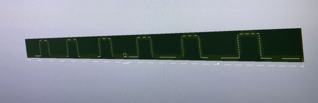
It took some time from my first design on meander dipole antenna, but last weeks I made further progress. Meander dipole is electricaly same length as dipole antenna but meanders make it physically shorter and they are able shift impedance to the sweetpot of Smith´s diagram.
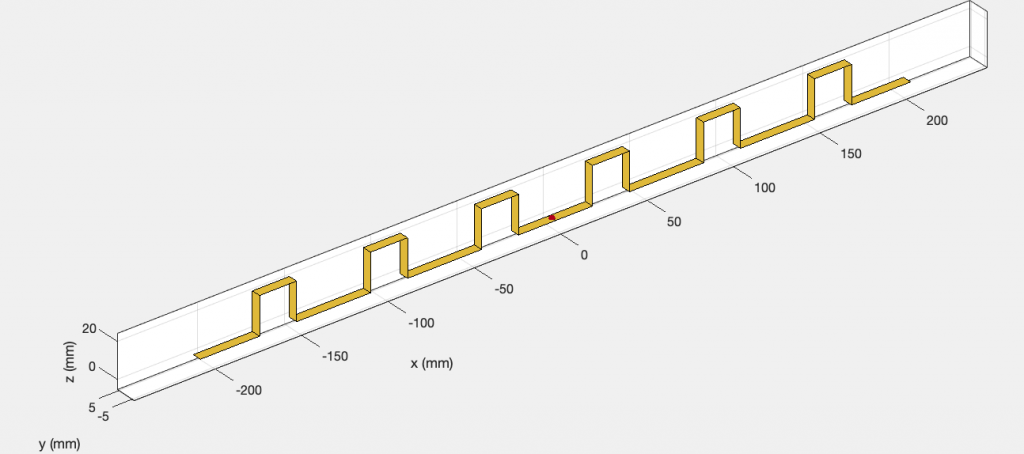
Big advantages of meander dipole antenna is near-perfect impedance match to power line and smaller size than physical. But of course there is disadvantage in lower radiation efficiency.
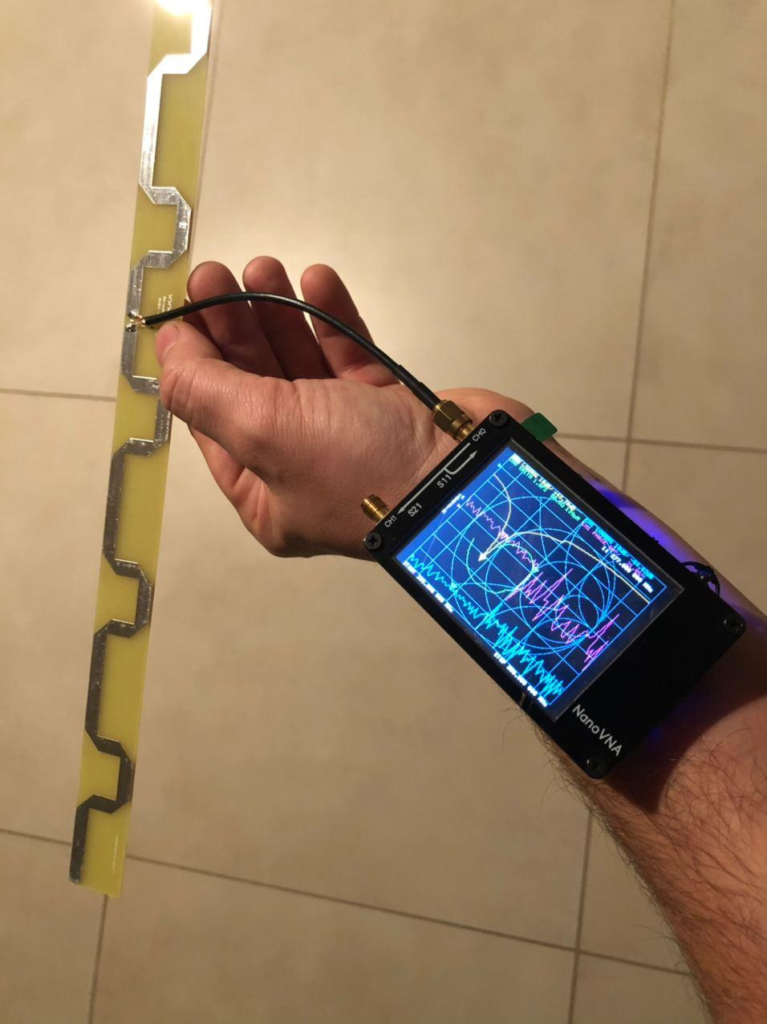
It looses about 8-12 % of efficiency which can be 0.7 – 1.2 dB which looks horribly but it certainly nulls the loss on full dipole because of impedance mismatch 73 + 43j Ohms to 50 + 0j Ohms.
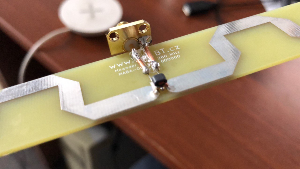
Further development was made on implementation of SMD baluns. Previous experiments with various types of ferrite rings were not successful. I discovered cheap wideband SMD made by MACOM [4] which is rated to 250 mW only. But if you dont mind over saturation of core it can work up to 4 W without heating HI.
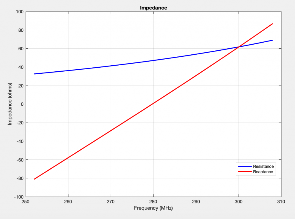
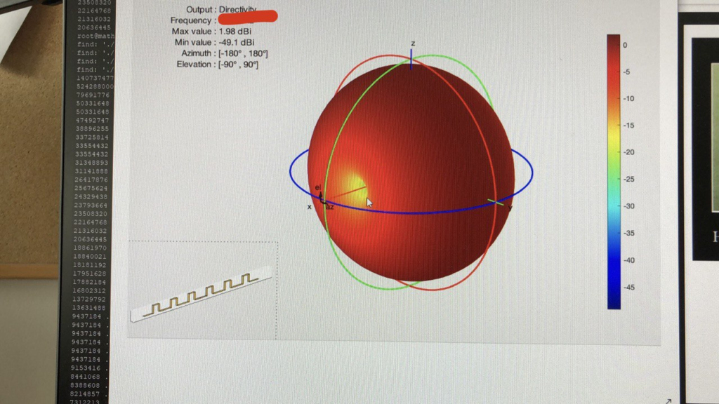
Model was made in AntennaDesigner toolbox from MATLAB. You can see that simulation of Impedance in Fig. 3 is nearly perfect antenna.
- https://www.mathworks.com/help/antenna/ref/dipolemeander.html
- https://www.qsl.net/kk4obi/Meander%20Dipole.html
- https://apps.dtic.mil/sti/pdfs/ADA617035.pdf
- MACOM / MABA-001759-000000